Solar thermal power stations; Upwind or up-draught chimneys
Background, principle
As for the wind also for the use of the solar power, different concepts are pursued. For both it is true that the electricity is usually not produced where and when needed. It must expensively be stored and passed on. Spread, particularly in Germany, are solar panels on buildings' roofs and on the free ground. They are a very expensive technical solution, which can be afforded only by substantial public support. It requires high technology, much energy and expensive rare materials for production.
As an alternative, solar thermal power stations are being developed and partly already built; also these are of a quite expensive technology. They are equipped with parabolic reflectors concentrating the sun light on tubes where it heats a liquid flowing inside, from which electrical energy is produced in classical thermal power stations. Also this approach is high-tech, it functions only with clear sky and strong sun, the energy storage is possible but not yet mature, its distribution expensive. (For instance for the project Desertec the electric current will have to be transported from north Africa via the Mediterrean to middle Europe.) As a further possibility the group of Schlaich and partners developed the theory for upwind power stations and concepts for their realization as large-scale installations: Fig. 11, Weinrebe. A smaller prototype was built in Spain.

Fig. 11 Up-draught and down-draught wind power station
In an up-draught or upwind power station, also called Solar Chimney, fig. 11 left, in a collector, that is a ground covered with plastic foil or glass, the air and the soil warms up by the sun. The warm air is led into a chimney (also called tower), in which it ascends, being accelerated by buoyancy of the warm lighter medium, thus driving one or more turbines. These are coupled to generators producing electricity. The energy is proportional to the product of area of the collector and height of the tower.
In the article Weinrebe/Schiel also down-draught wind power stations are described, in the fig 11 on the right. Water is injected into the upper opening of the tower, its evaporative latent heat cools the air, and it sinks and drives turbines at the foot of the tower. This is a conceivable solution, too, with the advantage that it does not need a large collector, however it needs much water. Since this usually is rare in warm dry regions, we decided for the upwind power station.
Our concept
The intention was to adapt the given principle to be realized in small installations, using minimalistic technology, meaning simple technical equipment and components available everywhere, ready for production and maintenance at lowest costs. The formulae developed for big power stations were down-scaled and simplified.
For the collector a sun-illuminated ground is covered with a transparent foil rising to one point. The foil is stentered on stretched rope or slats or bamboo staffs in such a way that no rain water puddle can form, by supporting the foil between the ropes or slats with additional springy posts. One can fix the foil at the edge to the soil, with openings for the inflowing air. Inside the collector, the foil can be placed high enough for persons to pass or work there. At the highest spot of the foil, the warm air gathers and is directed into the chimney. At the foot of the chimney there is placed an impeller, which is driven by the moving air. Its rotation is transformed into electrical current by a coupled generator, preferably a car dynamo. The energy is available in the living houses over a cable. Since in the warmed up soil, rocks or water containers additionally laid out, the warmth is contained there, electricity is produced also at night. This is reinforced when the ambient air cools down (particularly in desert areas). For further energy storage a battery could be used, however is not absolutely necessary. The chimney can be formed by either a plastic tube, erected and braced by ropes, or can be fixed to a tree, a rock, a building, where available. As a cheap alternative the chimney can be constructed by vertical bars (e.g. 4 pieces) with a foil wound around. In regions, where also storms (tornadoes, sandstorms etc.) can occur, collector and chimney are endangered. A free standing chimney must easily be put down, the cover of the collector easily removed or secured.
Expected performance
With a collector surface AK up to several 1000 m² and chimney heights H under 100 m, with appropriate optimization of the turbine, meaning that the pressure drop at the turbine is 2/3 of the entire pressure difference at the chimney, if it has appropriate diameter to be calculated by other formulae, with an ambient temperature of 25°C, one can expect a usable kinetic power Pmech according to the following formula:
Pmech = 1, 2 . 10-5 H . AK . G in [W] (1)
If H is given in [m], AK in [m²] and G in [W/m²].
For good efficiency of the then following transformation into electrical energy, the flow around the impeller is to be as little swirled as possible, develop few losses at edges and at alterations of the cross section. The generator, too, should have a high efficiency at the expected speed. For a power lower than 100 W the optimization of the generator appears problematic. If collector and chimney are accordingly laid out, then normal dynamos are suited.
Project at the Carl-Friedrich-Gauss High School in Hockenheim, Baden-Wuerttemberg
In the subject Natural Science and Technology (NWT) during the school year 2010/11 for pupils of the 10th grade the topic Upwind power station had been nominated. The task was to build a small model to prove the basic function of the upwind concept and an outdoor model to really produce a measurable amount of energy. 1000 m² were at disposal for the collector and a chimney height of 15m was permitted.
For more details please see the German version of this page!
Just a short summary here:
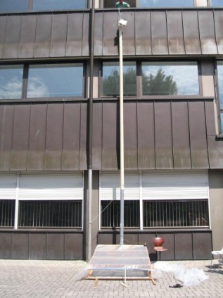
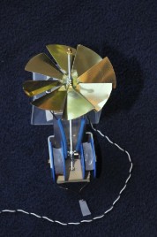
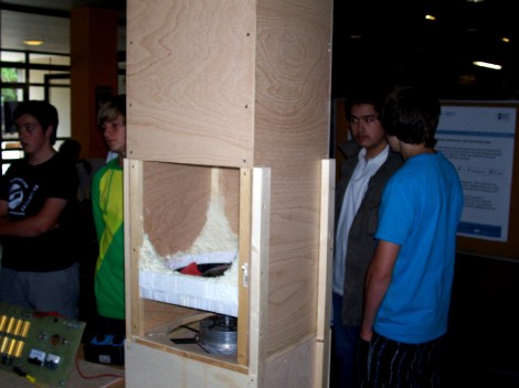
The small model was realized and functioned well (fig 14, 15). For the outdoor model the available time was too short to complete the whole installation. But we finished its central unit, where the air flow energy is transformed into electrical current (fig 16).
When finished, the model should produce approx. 126 W mechanical power, at an expected global radiation of the sun in central Europe of 700 W/m², a collector of 1000 m² and a 15 m high chimney. If an efficiency of the turbine plus generator of 50% is reached, thus approx. 60W of electrical power should be delivered, due to formula (1).
But of course some optimization process is needed. The goal of high efficiencies would be reached easier with a larger chimney and/or collector.
|
|
|
| Fig 14 Small model functioning | Fig 15 Small model, flow transformer | Fig 16 Outdoor model, central unit |